|
Contents
|
Basic idea
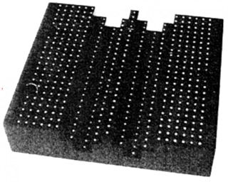
The most common way for calibration is to use a calibration target. The basic idea is to use a reference object with known coordinates. The calibration target should be seen by four cameras. The steps for calibration are stated below.
There are four folders in “working folder”.
- img
- parameters
- res
- calibration
Step I
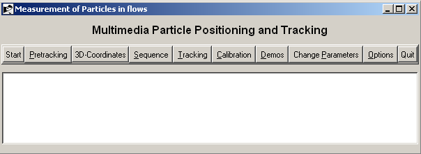
The main menu is shown in Figure-1. There are 10 sections. Choose “Change parameters” --> “Main Parameters” The parameters should be set as shown in Figure-2.
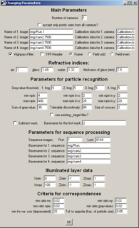
- Number of cameras = 4
- Name of 1.image=img/first image of the first camera
- Name of 2.image=img/first image of the second camera
- Name of 3.image=img/first image of the third camera
- Name of 4.image=img/first image of the fourth camera
- Calibration data for 1-4.camera=They should have the same path as the calibration images in calibration parameters
- Refractive indices --> air=1, glass=1.49, water=1.33
- Thickness of the glass should be chosen according to the experimental setup. (It is set to 7.5 mm for this experiment)
Step II
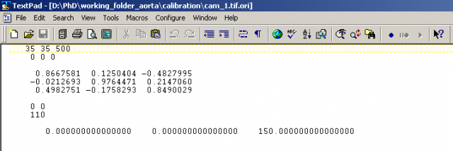
- Create four ori extended files for four cameras in Calibration folder. In the ori files copy the same parameters shown in the Figure-3. The ori files contains the coordinates of the cameras with respect to the reference calibration target, the camera angles and the focal distance. The first row is the camera position. The second row tells how the camera is rotated around x, y, and z-axis. The last number is very important: it tells the ‘focal distance’. How can it be guessed: In Our situation we have an ratio of “world image” to “Chip image” of 500mm to 65mm (384 pixels mal 17microns), e.g. 1:8. The distance from lens to calibration target is about 800mm. Hence our focal distance is about 100mm.
- Create a txt extended file named calblock.txt. This file contains the coordinates of the calibration target.
- Choose “Change parameters” --> “Calibration Parameters”
The parameters should be set as shown in Figure-4.
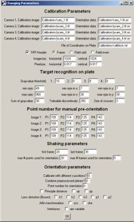
- Calibration data images for camera 1-4=Calibration/name of the image (copy the same path to Calibration data for 1-4.camera in Main parameters)
- Orientation data=Calibration/names of the ori files.
- File of the Coordinates on Plate=Calibration/calblock.txt
- Point number for manual pre-calibration: The numbers should be set as chosen in manual orientation.
Step III
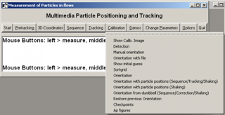
- Main menu in Figure-1 --> Calibration --> Show Calib. Image (Shown in Figure-5)
- Click Detection
- Click Manual orientation and choose four points for each camera. Once you have successfully done this you can check your clicks with the menu “Orientation with file”
- Click Show initial guess. The code shows you the initial guess. The yellow dots show where the dots from the calibration plane would end up on your images if the initial guess would be correct.
- To establish which detected point belongs to which calibration point click “Sortgrid”.
The parameters in the ori files will be changed. They are next to your initial guesses. The first six numbers are changed, i.e. camera position and orientation have been adapted. They will be used as starting values for the actual calibration in the next step.
- Repeat these steps until the yellow dots match with the points in the calibration images.
- Click orientation