
Establishment of stereoscopic imaging is the vital part amid settling other optical pieces for an experiment based on 3D-PTV. Two cameras are enough for stereoscopic focusing but four provides a welcome redundancy albeit not cost effective. A smart technique that spares the expense for the costly camera is to use image splitter having a shape of the pyramid. Instead of having four cameras, four mirrors assume the virtual camera role. Annexed figure here illustrates the idea.
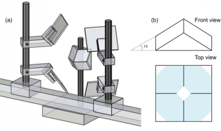
There exists no such a priori to set mirrors and stuffs and it could be enigmatic enough that someone may stress to have a hard and fast rule based on empirical observation. But pros and cons of the positioning of the individual optical tool with respect to the position of the setup itself is a function of the area to be focused. In this orifice experiment, observation area is approximately 20X 24 mm.
Proper magnification covering the observation domain accompanied by clean and equal focus from all four mirrors may lead to emerge overlapping problem of the images with each other. Here overlapping refers the blending of an image projected from one arbitrary mirror on to the image splitter with either its horizontal or vertical counterpart (or even in both direction). So mutual overlap from all four mirrors at the same time actually spoils the view of the flow domain as one particular image is interfered by the extent of other three images reflecting some extent of the flow and undesirably laying on to it.
What attributes most to this intricate issue of image overlap is the relative distance of the mirrors from the image splitter. Overlap in both direction can be effectively minimized (in some cases eliminated even) if the mirrors are placed away from the pyramid. Then obviously the mirror reflects the unnecessary parts of the flow geometry (where there is no flow, i.e., solid part) producing poor zoom in. This imposes the challenge to find an optimal position by continuously moving the mirror towards the pyramid up to the point where magnification and focus are satisfactory with non upsetting overlap. Here, one may define the non upsetting overlap as the extent of critical overlap from a mirror that stretches out (horizontally or vertically) but does not dilate so far to ruin the neighboring image; i.e., this overlap lays itself onto the solid part of the adjacent image causing no harm to flow visualization out there. This degree of overlap is tolerable as it does not necessitate masking the mirror. If higher magnification is on demand (as it was the case for orifice setup) then the mirror should come as close as possible to the pyramid making not only the whole arrangement quite congested but also allowing the previously innocent part of the overlap from the next mirror to grow and eventually swallow the image under scrutiny. So the definition of optimal position of the mirror does not always necessarily provide good enough magnification. Since at this point, magnification can not be compromised; the only measure left to eliminate the overlapping problem is to create a suitable mask on the mirror to make it appropriately partial blind. This task is sensitive to minute geometric precision of both mirror and pyramid surface and appeared to be painstakingly monotonic.
Once the whole optical setup gets ready to go certificate, it should remain untouched because the linear distances can be measured and saved but the angle of the mirrors on to the stand is difficult to measure and therefore to reproduce the system once again is close to nightmare.
Strictly speaking, this description surfaces from the experience out of orifice experiment and may get new face for another type of experimental effort.
As it happens in the laboratory
At the very beginning mirrors were tuned under low laser illumination for safety reason as it takes quite a while to get the right perspective. In this preliminary tuning stage the operating parameters were as such: camera frequency-50 FPS,laser-16 amp,camera aperture-16 and the consequent output is seen in the following figure.
.jpg)
In this arrangement,mirrors were placed so close to the camera objective (in order to achieve maximum magnification possible only on the zone of interest) that mirror clamps were almost brushing the lens. This became obvious as illumination is increased (but not full).A black part is seen engulfing every quarter of the image leaving the channel (and/or flow domain) obscure. This unwanted black part onto every images arose due to the intimate placement of the mirror to the camera which caused mirrors to reflect objective surface and overwhelm the image all over.
.jpg)
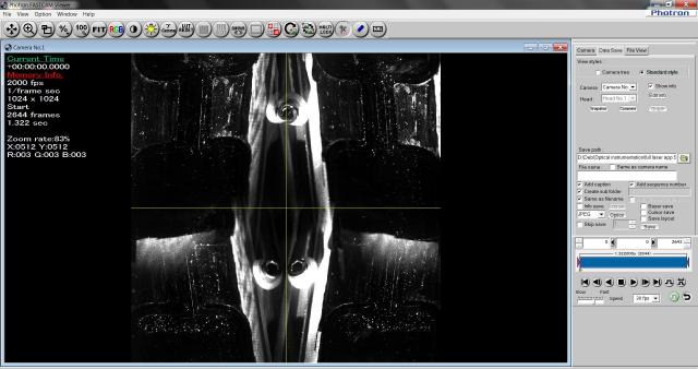
So mirrors were dragged away to produce undisturbed image as seen here.
.jpg)
Up to this point, all the distances and angular position of the mirror are assumed to be the best possible set and subject to leave as it is. From this figure we can infer something about orientation of the mirrors and the much anticipated overlap.
A closer look on the two screws seen at the bottom mirrors gives the evidence of almost identical inclination of those mirrors as it is also the case for the upper two.
The bottom quarter of the images certainly intrudes to each other by their edge but definitely do not reach out to the important flow regime. This two images are also swept over vertically by a narrow margin from the upper quarter but again that extent of vertical overlap does not hamper the channel view all the way. This particular figure exemplifies the concept of optimal image overlap that does not require any external mask on the mirror but with an expense of relatively lower zoom in.
After these time consuming adjustments,its time to examine the setup under desired operating conditions, i.e., full laser illumination as well as required temporal resolution(2000 FPS for this experiment).Even at full laser power, image seen at 2000 frame/sec at aperture 16 is quite dim and henceforth it was bound to tune low aperture number allowing more light to come through.
.jpg)
Lower aperture allows not only more light but also enhances reflection from the surface. This is evident in figures below. Camera aperture was 5 and 2.8 in the figure left and right respectively.
.preview.jpg)
At this point one can now fiddle around with the camera option like “color adjustment” including parameters such as gain,gamma,contrast and brightness together with the “Additional feature” that facilitates to shift the bit.
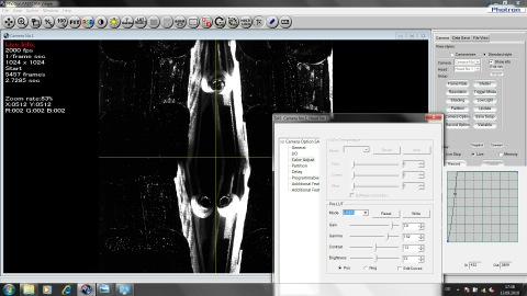
After careful manipulation the final image appeared as in figure.
.jpg)
This is only a quick and dirty explication about what are the major challenges on the way to derive a clear image in accordance with demands in hand and how to prevail over those problems. Although detrimental reflections
stand still in this orifice experiment which is quite stubborn and a way to get rid of the reflection is a must.